The Hurst Simulator
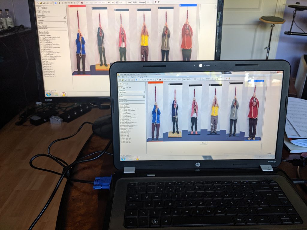
As of June 2019, a ringing simulator has been available at St. Nicholas Hurst bell tower . The local band use this with a laptop running (currently) Abel. However, we have specifically set the simulator hardware up so that it can used by visiting ringers who bring their own laptop and software.


What is a “Ringing Simulator”?
A ringing simulator describes an installation where the bells are instrumented with sensors which are then wired into a computer in the ringing chamber running an application which supports a number of useful training aids. When each of the real bells is rung, a signal is sent to the PC application. Typically the PC application provides a software simulation of the bells and ringers. Commonly used applications are Abel, Virtual Belfry, and BelTower.
This sort of simulator setup can be an invaluable teaching tool, supporting a number of useful capabilities including:
- Quiet or silent ringing using muffled or tied bells
- Ringing on more bells than the tower has, or has ringers for
- Striking accuracy exercises and analysis
- Bell control exercises
- Ringing technique practice
- Call changes exercises
- Learning methods
History
The idea of a “ringing simulator” was mooted at one of the “practice debrief” sessions in the Castle Inn across the road from the St. Nicholas Church tower by Graham, the Tower Captain back in 2018. At this time, the band were all quite new having mostly been recruited for the Ringing Remembers campaign. The idea was discussed and links to resources exchanged, and this led to the construction and installation of a simulator in the St. Nicholas Church tower over the following months.
The Build
For the months following this initial discussion some of the band did some more research on what was available and what would be required.
Of particular interest was the Liverpool Ringing Simulator Project, an open source, open hardware design based on work undertaken at Liverpool Cathedral with the stated aim of “producing and publishing designs, software and documentation to enable other towers to build and install their own simulators at relatively low cost”. The designs, documentation and software for this are all freely available under various Open Source, Open Hardware, and Creative Commons licences. This includes comprehensive build and installation documentation.
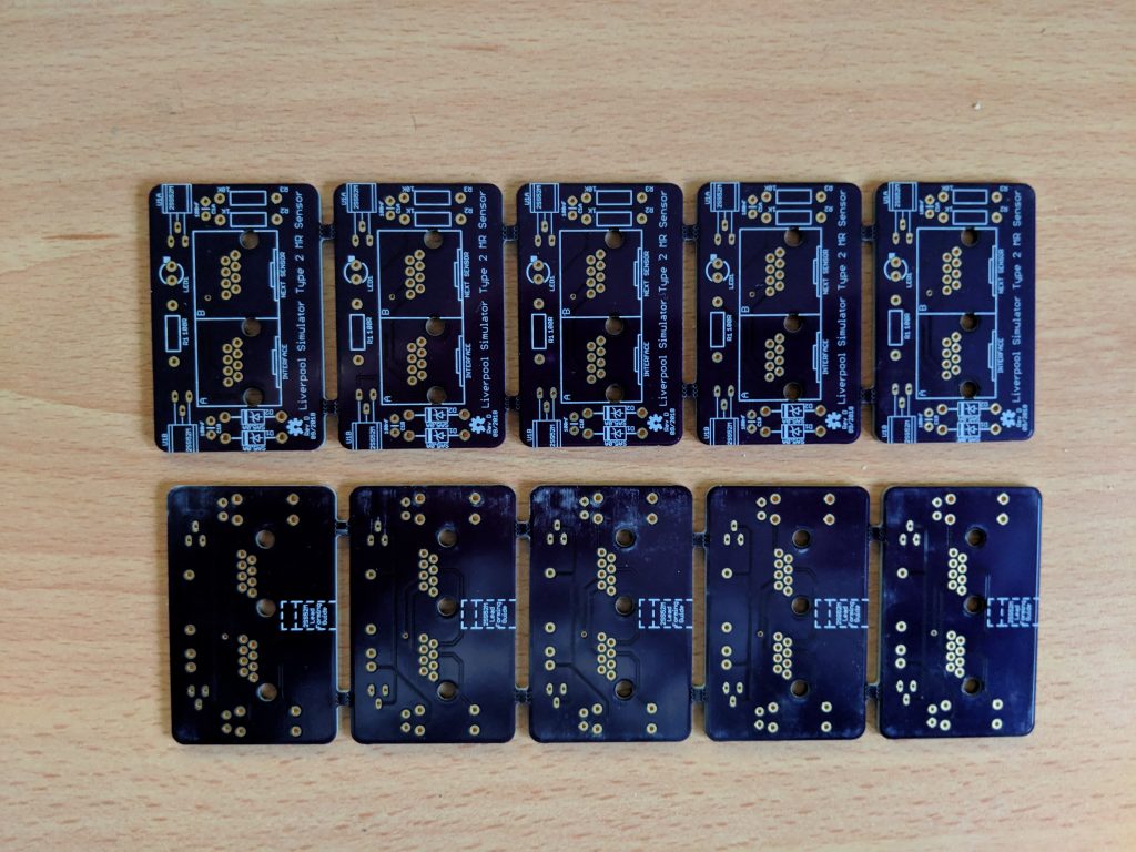
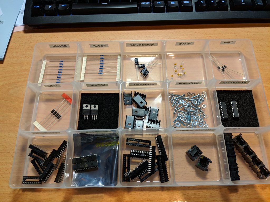
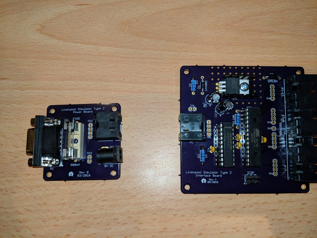
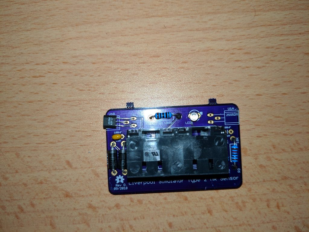
One of the new recruits in the Hurst band was a qualified Electronics Engineer who quickly understood what was required, so printed circuit boards (PCBs) were ordered along with electronics components and strong magnets for the sensors. These were then assembled, and soldered.
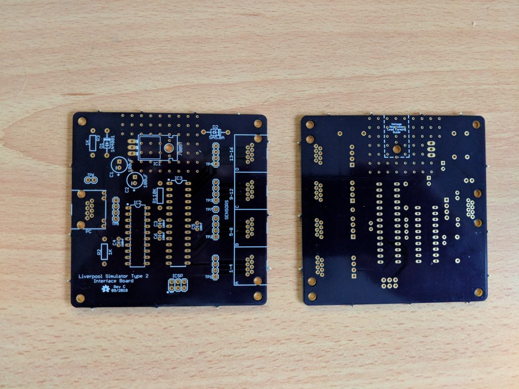
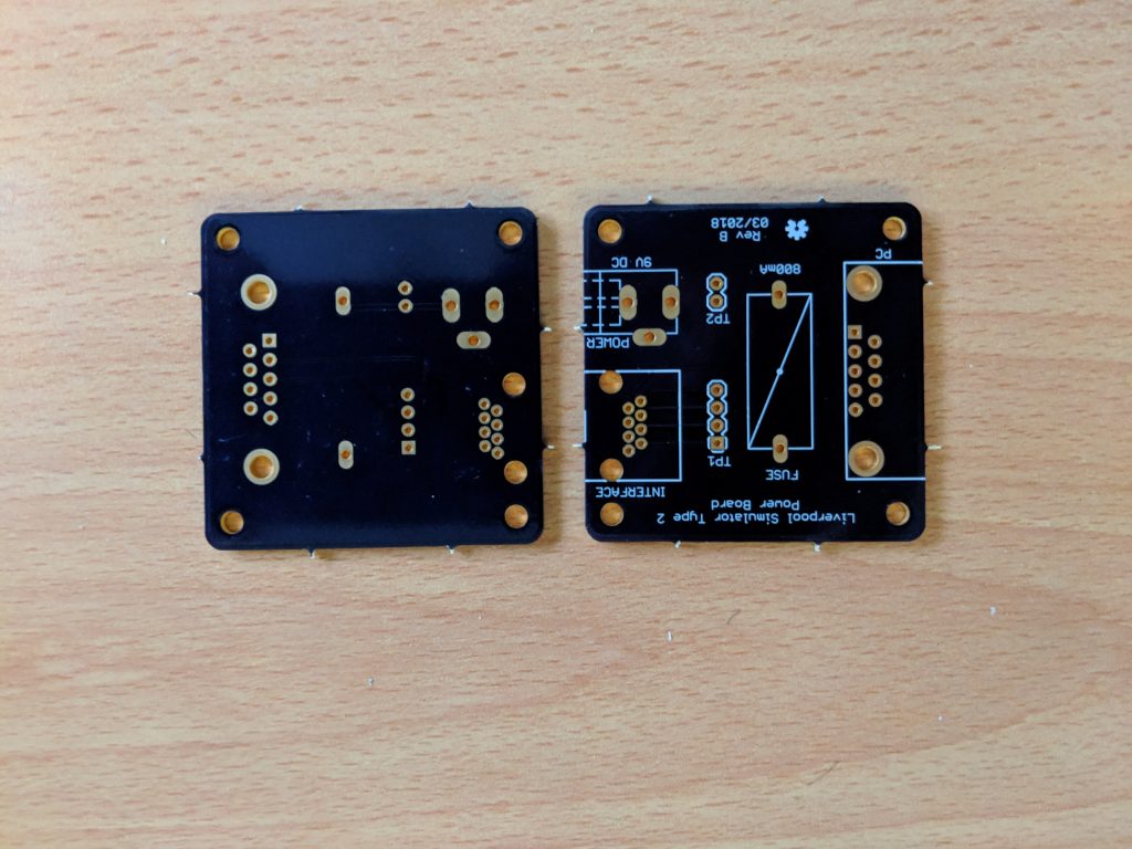
One of the more challenging parts of the build is the programming of the microcontroller on the Interface board. This requires an external programming interface to be connected in order to download the code onto the microcontroller.

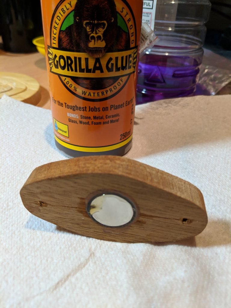
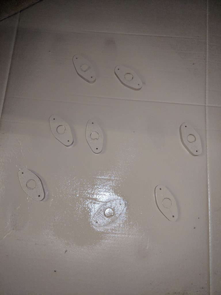
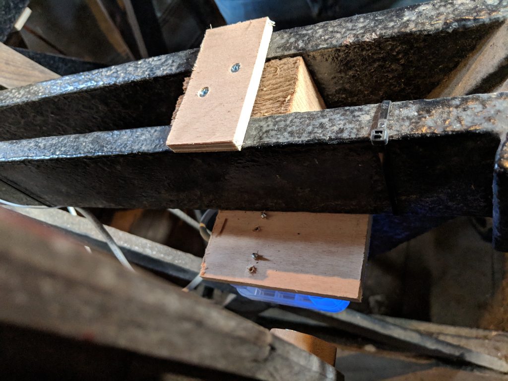
Wooden mounting blocks for the magnets were constructed, and the magnets glued in. These were then spray painted with plastikote to preserve them and keep out moisture.

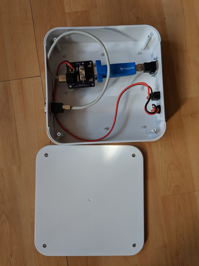
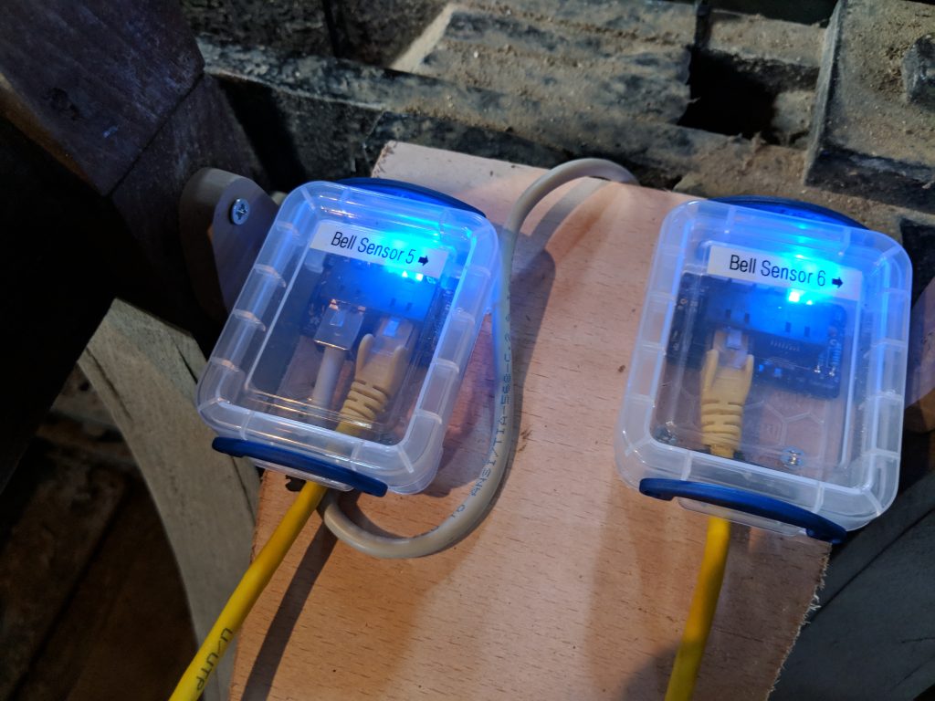
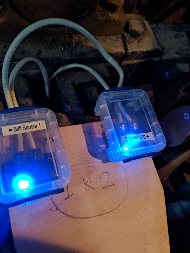
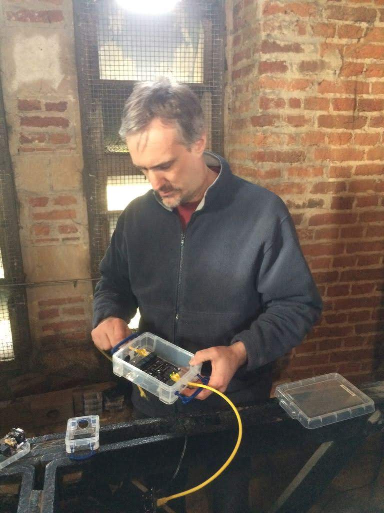
As recommended in the Simulator build instructions, a range of Really Useful Boxes were used to hold each of the printed circuit boards. Holes were drilled in these to allow the wires to be connected, with grommets inserted to keep dust (and spiders) out of the boxes. The system was then wired up and tested, with each sensor being tested for function and also sensitivity. The whole system was then tested with Abel.
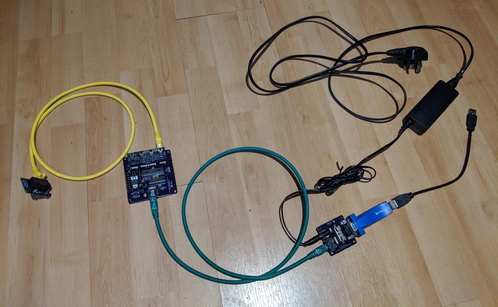
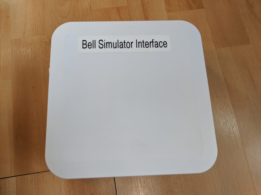
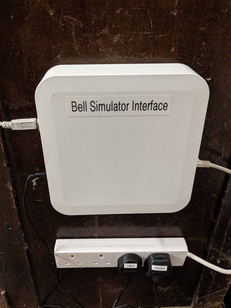
An enclosure was constructed to be located in the ringing chamber. This contains the main power board plus power connectors and a USB to serial interface so that a PC can be connected to the system with a USB cable.
The Installation
The installation into the tower was done on 6th June 2019 by Graham (the Tower Captain) and Keith.
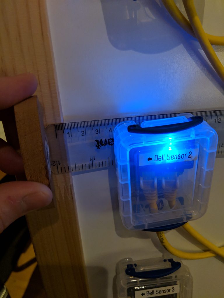
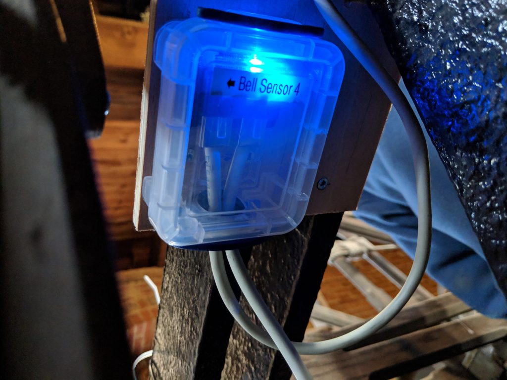
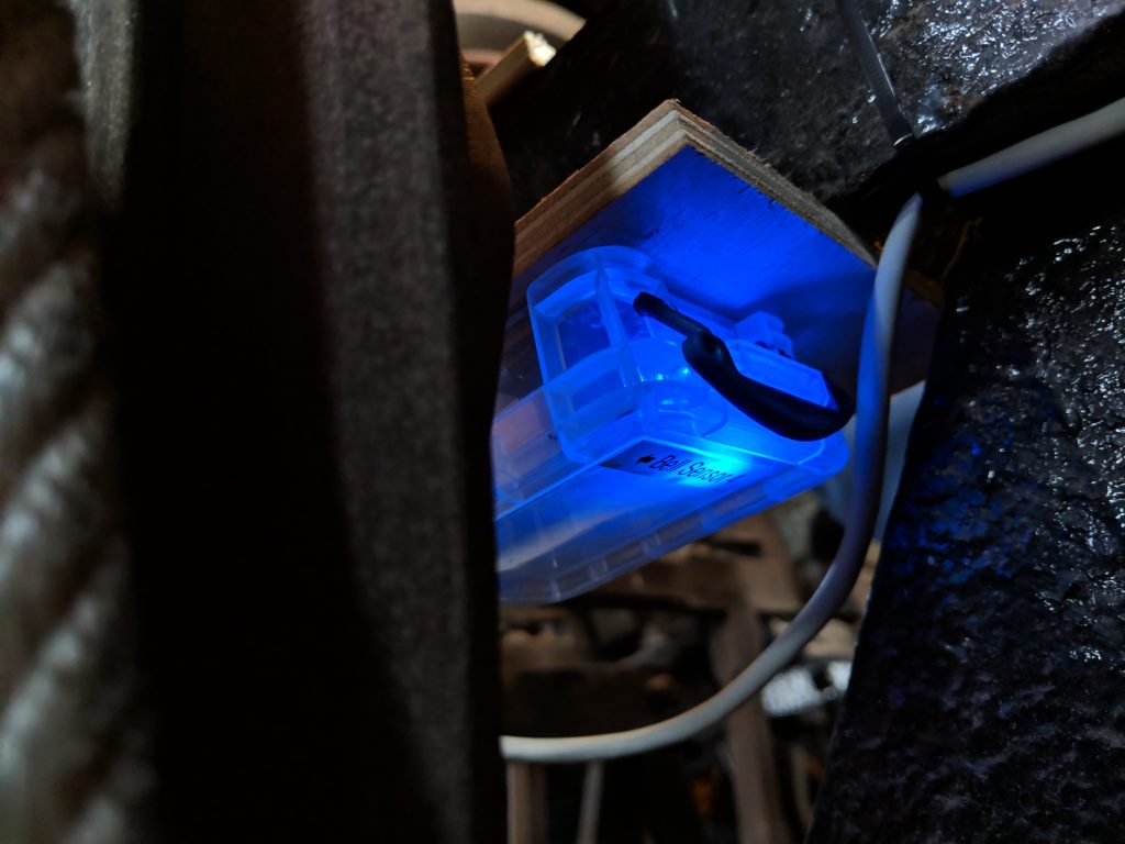
The wooden magnet holders were attached to the outer rim of each wheel. Graham had fashioned some wooden brackets which could be attached to the bell frame allowing each of the bell sensors to be attached near to the wheel.
The simulator allows the sensors to be connected in a daisy-chain fashion. Custom RJ45 patch cables were created for this, linking from the main simulator box to each of the bells.


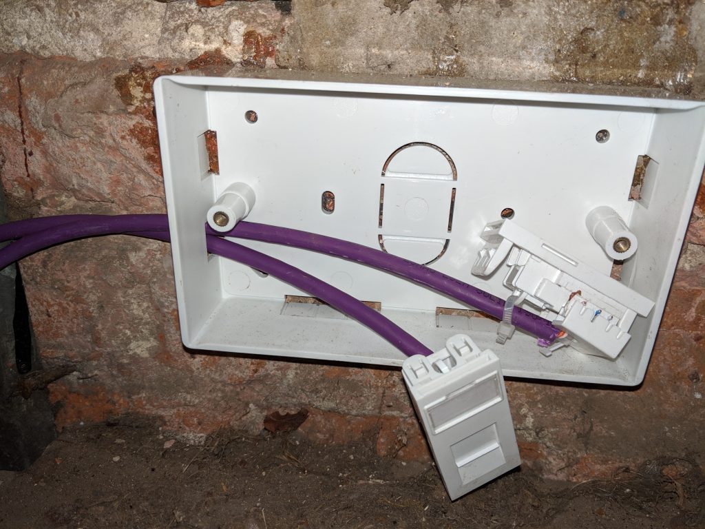
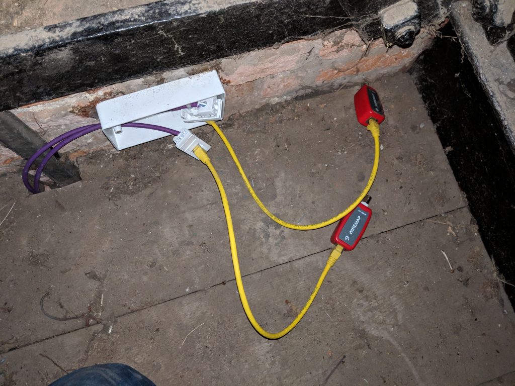
The cabling between the ringing chamber and the belfry is a pair of cat 6 cables, terminating in RJ-45 sockets at each end. One of these is for the simulator, whilst the second is to be used for a CCTV camera. The cabling was run in conduit up the walls. The simulator is connected using RJ45 patch cables at each end.

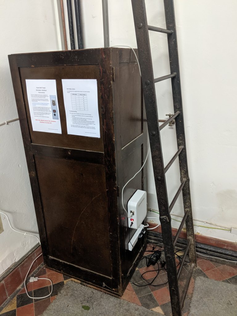
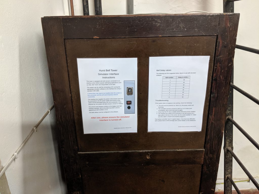
Finally, the box was installed in the ringing chamber, along with some instructions.
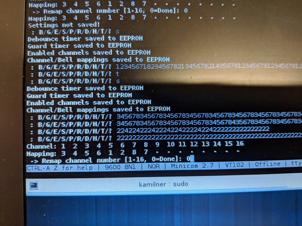
The system was tested and set up. Primarily, the bells needed to be remapped as the order they were connected via the daisy-chain cables is not the order of the bells.